- What is the difference between closed loop and open loop?
- Which is better shunt or Hall effect current sensors?
- What is the difference between single supply and dual supply?
- How to derive voltage output from closed loop?
- How do I check sensor is working correctly or failed ?
- What is nominal value and measuring range?
- How is the minimum and maximum value of burden resistors determined?
- What is current consumption?
- What is creepage and clearance mean?
- What is polarity of the transducer?
- What is response time of a transducer?
- What is split core current sensors?
- How do I increase output signal of current sensor/ current transformer for a given input current?
- What happens if I apply single supply to a dual supply sensor or vice-versa?
- Do we have reverse protection for current sensors and voltage sensors?
- What is the frequency response of current/voltage sensor?
- What is offset and its implication?
- Are products UL approved, CE certified & RoHS compliant?
- What is temperature drift of offset and gain?
- What is linearity error and accuracy?
- Why is a hall effect current sensor preferred over resistive shunt for measurement of direct electric current (Unidirectional current)?
- What is a instantaneous output sensor and conditioned output sensor?
- What is the difference between closed loop Hall Effect current sensor and open loop current sensors?
What is the difference between closed loop and open loop?
Open Loop Hall Effect current transducers
A current carrying conductor creates a magnetic field. This field is concentrated by a magnetic core. The core has a gap cut through it and a hall generator is used to sense the magnetic flux density in the gap. The control current, IC, and Differential amplification are supplied by electronics (Fig. 1 built into the transducer).
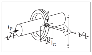
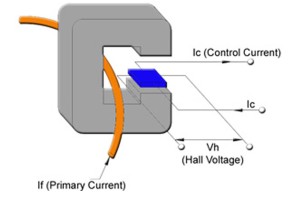
Fig 1: Conversion of the primary current into an output voltage.
Closed loop Hall Effect current transducers
Compared to the open loop transducer, Hall Effect closed loop transducers (also called Hall Effect ‘compensated’ or ‘zero flux’ transducers) have a compensation circuit that dramatically improves performance. While open loop current transducers amplify the Hall generator voltage to provide an output voltage, closed loop transducers use the Hall generator voltage to create a compensation current (Fig. 2) in a secondary coil to create a total flux, as measured by the Hall generator, equal to zero. In other words, the secondary current, IS, creates a flux equal in amplitude, but opposite in direction, to the flux created by the primary current.
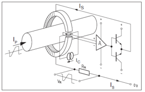
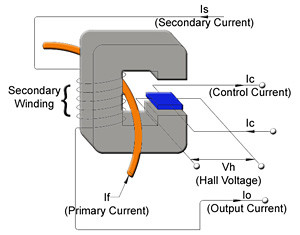
Fig 2: Operating principle of the closed loop transducer
Operating the Hall generator in a zero flux condition eliminates the drift of gain with temperature. An additional advantage to this configuration is that the secondary winding will act as a current transformer at higher frequencies, significantly extending the bandwidth and reducing the response time of the transducer. When the magnetic flux is fully compensated (zero), the magnetic potential (ampere-turns) of the two coils are identical. Hence: NP • IP = NS • IS which can also be written as IS = IP • NP / NS. Consequently, the secondary current, IS, is the exact image of the primary current, IP, being measured. Inserting a „measurement resistor“, RM, in series with the secondary coil (Fig. 2) creates an output voltage that is an exact image of the measured current.
We have listed below a few of the questions , pertaining to the products in our manufacturing range along with our answers . Should you require any other clarification kindly fill a from through submit a trouble ticket